Stopped is not the same as isolated
A stopped machine can still hold energy
A stop button may stop normal operation without disconnecting energy. Electrical supply, pressure, gravity or spring force can still permit movement after another command or a change in conditions. Maintenance and cleaning require separate consideration of stopping, isolation, stored energy and verification.
LOTO is not a count of padlocks. It identifies and isolates sources affecting the job, controls restoration by others and deals with residual hazards. A tag without a defined isolation boundary does not establish a shared understanding between workers and operators.
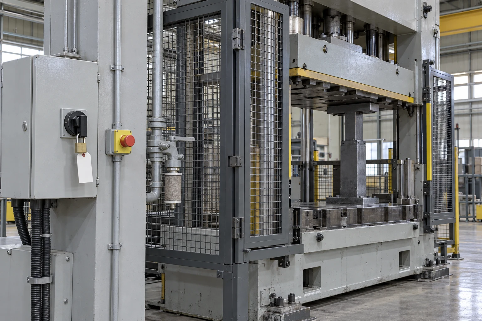
- Isolator lock: Identify and isolate the supplies reaching the work area, then control the lock against re-energisation during maintenance.
- Stop button: After stopping the machine, check the separate energy-isolation points and remaining energy.
- Pneumatic piping: Trace the connected supply and check the isolation points and procedure for releasing residual pressure.
- Mechanical support: Before approaching beneath a part that could descend, check the support installation and restraint.
A command is different from separation
An operating button can send a stop signal without physically disconnecting every energy source. Remote or automatic commands may remain relevant. A stopped indication on the control screen and absence of energy at the maintenance point require separate verification.
Disconnecting electricity can leave compressed air able to move a cylinder or gravity able to lower a raised part. Depressurising can itself remove a supporting force. Equipment-specific procedures must therefore define support or restraint and the sequence of energy control rather than prescribe universal pressure release first.
Closing one valve may leave other connections or bypasses effective. Include stored energy in tanks, accumulators and hoses within the assessed boundary. Normal operating flow alone may overlook backflow or another supply during maintenance. Reconcile drawings with the installed equipment.
Verification must suit the equipment and fluid. One zero gauge reading does not prove every compartment is depressurised; consider restrictions, isolation between gauge and work point, and separate storage. Loosening bolts to test for release can introduce danger and is not a substitute for a safe defined method.
Figure 2 highlights the checks described here.

- Electric supply: distinguish stopping from isolating the supply to prevent restart.
- Reservoir: identify energy that can remain after supply isolation.
- Raised part: consider mechanical support against descent.
- Work area: trace the isolation boundary back from actual access.
Preparation: trace back from the work point
Start with the part where hands or bodies will be exposed, not merely the machine name. Identify movement, falling, pressing or release paths, including connected equipment, shared supplies and automatic transfer. Match physical identification to the actual job boundary.
Then identify normal stopping arrangements and isolation points. Normal stop, emergency stop and isolation serve different functions. Clarify the devices involved and involve appropriate operating and maintenance personnel so that workers do not improvise electrical or process interventions outside their competence.
Control who may remove the protective locking or tagging arrangement. A key left beside the equipment undermines restart prevention. For multi-person work, the procedure must prevent one person’s completion being mistaken for everyone’s release.
Execution: stored energy and verification hazards
Do not omit non-electrical energy. Pneumatic and hydraulic sources can move components as well as release fluid, while raised parts can descend after disconnection. Provide necessary mechanical support or restraint and keep people out of pinch points during energy removal.
Verification itself can create movement. The procedure must address personnel clearance before a test and the control state afterwards. A try-start record does not establish control of every energy source. Electrical testing belongs under the relevant electrical procedure and competence requirements.
Review isolation if the job changes. Work outside a cover may turn into entry to clear a blockage, changing exposure. Opening another connection or moving another device requires reassessment rather than assuming the original locks cover it.
Hand over isolations and outstanding work at shift or team changes. When the person who stopped the equipment is no longer present, the reason for a lock can become unclear. Maintain identifiable current work and removal authority rather than anonymous tags or obsolete lists.
Distinguish Article 92 from electrical Article 319
Article 92 addresses stopping for hazardous maintenance, cleaning, inspection and repair, preventing restart, and hazards from compressed gas or liquid. Read paragraph 2’s wording on locking, key control or signs with the need for appropriate protection. A sign does not physically interrupt energy flow.
Article 319 addresses de-energised electrical work, including disconnection, opening, locking and marking, discharge and testing. A simplified machinery LOTO diagram does not replace that procedure. The KOSHA 2020 educational sheet helps explain stages; the actual isolation plan requires current provisions and equipment procedures.
Field practitioner note: the isolation-valve tag
Different energy means different verification
A stopped rotating part can still receive force through a connected shaft or machine. Establish whether isolating one motor controls the full work boundary, including auxiliary drives and automatic transfer that may be less obvious during normal operation.
Closing the air supply differs from controlling downstream trapped pressure. Blocked vents or isolated compartments can require separate verification. Understand whether a gauge and the work point share the same pressure zone before interpreting the indication.
A hydraulically raised component may descend when pressure is released. Calling hose disconnection “depressurisation” does not make it safe without support. Assess movement and restraint first and apply the equipment procedure with people clear.
Springs and suspended loads may have no obvious supply line. Disconnecting cables and hoses does not remove their force. Equipment knowledge is needed to assess release directions and provide restraint before components are loosened.
Hot equipment can injure without movement. Stopped operation does not mean cooling is complete, so define thermal access conditions separately. Mechanical isolation and temperature verification should not be collapsed into one undifferentiated check.
Article 319’s restoration provisions include checks on equipment removal and safe personnel positioning before energisation. An absent key holder calls for defined authority and procedure, not casual removal to meet a schedule.
Temporary energisation for testing changes the work state. Define the test boundary and personnel positions and re-establish protection before re-entry for adjustment. The label “test run” does not justify unrestricted simultaneous operation and maintenance behind an open guard.

Reconcile people, equipment and records before restoration
At completion, account for tools, parts, guards and people. Remove controls only under the defined authority and sequence, without casually removing another person’s protection. If adjustment is needed during testing, return to the required stopped and isolated condition.
Testing and normal restoration may finish at different times. Check removal of temporary connections or bypasses before normal operation. The following table links verification through isolation and restoration; it does not replace the equipment procedure.
| Point | Question | Follow-up |
|---|---|---|
| Sources | Are there other connections or auxiliary supplies? | Match the physical boundary to drawings |
| Stored energy | Could depressurising move a component? | Identify restraint and a safe release sequence |
| Verification | Does the method establish conditions at the work point? | Check indication location, compartments and personnel clearance |
| Restoration | Are temporary connections, tools, people and guards accounted for? | Separate normal restoration from testing and re-isolate for adjustment |
One switch cannot describe every machine
Isolation points, depressurising methods and support capacity depend on design and manufacturer information. A wrong source assessment can leave danger despite a lock. Pause the work and obtain competent review for an unresolved connection.