Process safety & fire/explosion protection · Korean law and international manufacturer references
Gas passes, flame stops: how flame arresters work and where they are used
From Davy’s lamp to industrial quenching: element and installation-inspection illustrations, breather valves, selection and maintenance explained.
Product information
| Also called | Flame arrester / flame arrestor |
|---|---|
| Purpose | Permit gas flow while arresting flame under specified conditions |
| Selection | Gas properties, location, flame regime, pressure, temperature and flow |
| Scope | Metal-element technology, not a recommendation of a particular product |
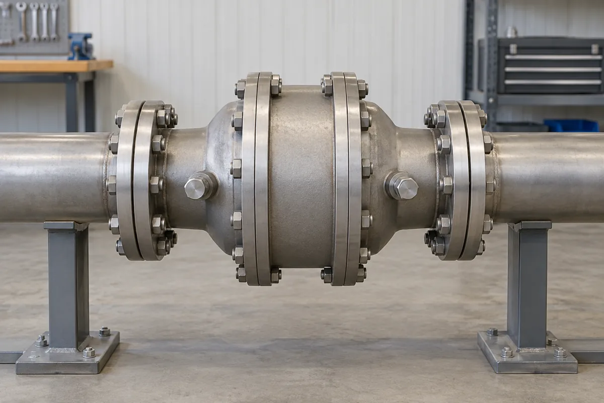
- Flange joint: compare gasket and bolt reassembly with the applicable manual after inspection.
- Housing: Before inspection, identify the assembly and check its internal element using the inspection procedure in the applicable manual.
- Access space: check room for removal and maintenance instead of assuming installation alone provides access.
Two centuries of one physical idea
From lamp gauze to engineered narrow passages.
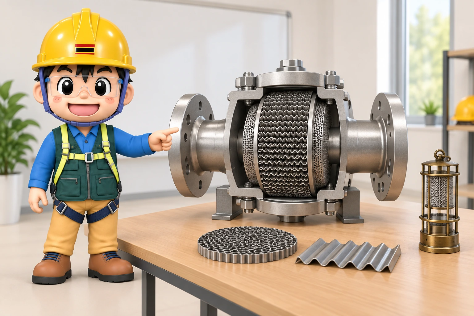
The educational cutaway illustration does not reproduce a specified product or installation.
Use actual product drawings and instructions for selection and maintenance.
1. Davy’s safety lamp: admit air, contain the flame
A naked lamp could ignite a flammable methane–air mixture in a mine. Humphry Davy’s 1815 lamp surrounded its flame with metal gauze. Air could enter while heat transfer to the gauze inhibited flame transmission under appropriate conditions.
This is not gas filtration. Quenching removes enough heat from the reaction in narrow passages. The historical lamp explains a principle; it is not a substitute for modern lighting suitable for a hazardous area.
Sources: Royal Institution · Humphry Davy’s miners’ safety lamp
2. Cooling does not always require water
Water-based cooling and a metal-element arrester both remove heat, but the receiving medium and protective objective differ.
| Feature | Water-based cooling | Metal-element flame arrester |
|---|---|---|
| Medium | Water | Metal element |
| Action | Heating and evaporation absorb heat | Heat transfers to passage walls |
| Purpose | Suppress the target fire | Prevent flame transmission across the device |
Water can also have other effects, including oxygen dilution in some conditions. This comparison concerns cooling. An arrester is neither a gas shutoff valve nor a general fire-extinguishing system.
3. What happens inside the element?
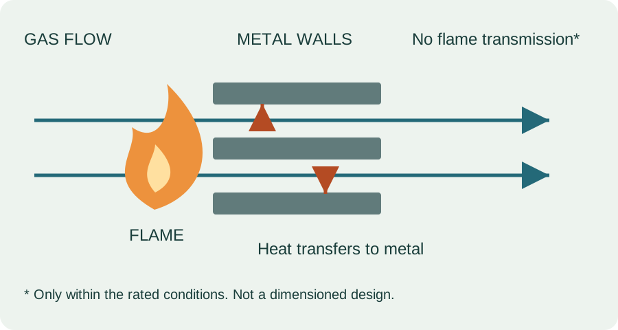
Winding flat and corrugated metal ribbon together creates many narrow passages. Heat transfers from the flame and hot gas into their walls. Sufficient heat loss prevents the combustion reaction from continuing through the element.

- Flame and hot gas arrive
- Heat transfers into metal walls
- Conditions for sustained combustion are lost
- Flame transmission is arrested
A flame is not a large particle caught by a sieve. Gas flow and a propagating chemical reaction are different processes. Passage dimensions, gas properties, pressure, temperature and element condition all matter.
Sources: PROTEGO · Flame arresters
4. Match the device to the flame scenario
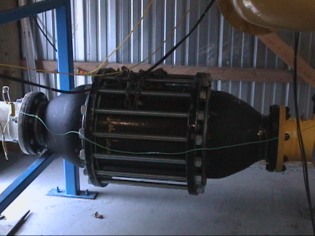
An external flame at an open vent is different from a flame travelling through a pipe. A deflagration rating does not establish detonation protection; an end-of-line device must not be repurposed as an in-line unit.
| Type or duty | What to check |
|---|---|
| End-of-line | Open termination and external-flame conditions |
| In-line deflagration | Manufacturer limits on pipe length, configuration and ignition source |
| Detonation | Applicable detonation conditions, gas, pressure and temperature |
| Stabilized burning | Short-time or endurance-burning rating and monitoring/shutdown requirements |
Deflagration propagates subsonically relative to the unburned mixture; detonation is supersonic combustion coupled to a shock wave. Where a pipe can accelerate the flame, the design assessment must address that possibility. Check the permitted pipe length against the specific product’s conditions of use.
Arresting a passing flame and tolerating a flame that continues to burn on the element are separate duties. Continued heat input raises element temperature: check the applicable burning-time limit and protective response.
Sources: PROTEGO · Technical fundamentals / Safe systems in practice
5. Applications and the breather valve
A pressure/vacuum breather valve manages tank breathing during filling, emptying and temperature changes. An arrester limits flame transmission through that path. Products may combine the functions or use separate devices; the name alone does not establish both capabilities.
| System | Protection to consider |
|---|---|
| Flammable-liquid tank | External flame ingress through the vent system |
| Vapour recovery or transfer | Flame transmission between connected equipment |
| Waste-gas combustion or flare | Protection of the supply system where required by the design |
| Biogas or digester gas | Manifolds, desulphurisation units and combustion equipment connections |
Manufacturer examples describe possible systems, not an instruction to put an arrester in every flare line. Review substance properties, blockage, discharge capacity and the overall protection design.
Valve set pressure is only part of the assessment. Include the pressure losses across piping, valves and the arrester when checking breathing capacity. Making passages smaller is not always a better solution.
Sources: PROTEGO · Biogas, wastewater and landfill gas systems · Emerson · Tank pressure and flame protection
6. South Korean requirements: a generic vent valve is not enough
Article 268 of South Korea’s Rules on Occupational Safety and Health Standards addresses venting equipment, sufficient venting capacity and maintenance for atmospheric tanks handling flammable liquids. Article 269 establishes installation of a flame arrester at the top as the general rule for preventing external flame entry when the relevant chemical equipment releases flammable vapour or gas to the atmosphere.
Article 269(1) includes exceptions for a vent line equipped with a flame-preventing vent valve, or for flammable liquids with flash points from 38°C to 60°C inclusive where a flame-preventing mesh is provided. A generic breather valve or improvised mesh does not by itself demonstrate compliance.
Article 269(2) requires installation conforming to the relevant Korean Industrial Standards criteria for flame-arresting devices and thorough maintenance. Determine applicability by checking the equipment, substance and operating conditions together with the current original provisions. Foreign certification alone does not automatically establish Korean statutory conformity.
KOSHA’s flame-arrester prevention leaflet references Guide P-70-2019. Distinguish guidance and manufacturer recommendations from law. Confirm the applicable standard edition and product evidence rather than inferring compliance from this overview.
Sources: Korean National Law Information Center · OSH Rules · KOSHA · Flame arrester incident prevention
7. Blockage affects breathing as well as flame protection
KOSHA describes a 2023 South Korean wastewater-tank event in which a blocked vent arrester prevented pressure relief and the tank roof ruptured. Presence of the device did not establish continuing protection.
KOSHA advises inspection and cleaning for blockage, corrosion, deformation and damage, with shorter intervals where deposits can build rapidly. Consider condensation and freezing as well as the actual product instructions.
For example, the Enardo EN-7 manual calls for damage inspection following deflagration or stabilized burning and a cleaning interval informed by fouling. Its cleaning pressures and allowable gap dimensions must not be generalized to other models. Establish safe isolation and depressurization before maintenance; do not replace an element with improvised mesh.
Sources: KOSHA · Flame arrester incident prevention · Emerson · Enardo EN-7 instruction manual
8. Apply it on site: selection through reinstatement
This editorial workflow helps organize a competent assessment using the actual certification, design and instructions. It is not a fabrication or modification procedure.
- Define gas composition and normal/upset conditions
- Identify ignition sources, flame paths and protected equipment
- Match location, flame regime and burning duty
- Check capacity, pressure loss and installation limits
- Plan inspection, reinstatement and change management
| Question | Evidence to review |
|---|---|
| Which side is protected and where can ignition occur? | Piping drawing, orientation and model instructions |
| Have the gas or operating conditions changed? | Design basis, rating and change records |
| Does tank pressure change during transfer? | Breathing assessment and operating trends |
| Is there blockage, corrosion or deformation? | Inspection, replacement element identity and specification |
| Was the assembly properly reinstated? | Manufacturer reassembly/leak-check requirements and responsible person |
An unverified rating is a reason to withhold a conclusion of protection. After pressure anomalies or flame exposure, investigate and use the approved procedure to decide on continued operation, shutdown or reinstatement.
Technical insight
Manage flame arresting and breathing capacity together
Narrow passages transfer heat from the flame but also resist gas flow. Selection therefore needs to establish both flame protection and the required breathing capacity within the tank’s allowable pressure range.
As an editorial field practice, link each device identifier to its gas duty, location and maintenance record. Review both flame rating and pressure loss when components or piping change, and retain evidence of correct reinstatement after element removal or cleaning.
Model-specific test scope and maintenance
Figure 2 identifies visible inspection locations. The conditions not visible are listed below it.

The April 2026 edition of Enardo EN-7 manual D103584X012 identifies this model as a bidirectional in-line deflagration arrester, not a detonation arrester. Match the expected flame regime to this test scope rather than relying on the product name.
Its short-time burning limit under atmospheric conditions is 1 minute. This is not an unlimited endurance-burning rating. Detection and shutdown must act within the permitted burning time, and replacement temperature sensors must retain the required response characteristics.
The instructions address pressure-tap monitoring for blockage and space for inspection. Cleaning intervals depend on deposit accumulation and cannot be assigned one universal fixed interval. The element requires immediate inspection after deflagration or stabilised burning.
The element bank is treated as an assembly rather than being dismantled from its shell, and the specified procedure requires gasket replacement after separation. Enlarging or machining passages is not cleaning. Confirm orientation, identification, fastening and leak checks in accordance with the product instructions.
Check placement and venting on the same system
Required venting must accommodate filling, emptying and temperature changes. Include losses through the valve, piping and arrester. Correct breather settings do not ensure acceptable tank pressure or vacuum if another part of the path is obstructed.
Compare marked gas group, operating pressure and temperature with the actual service. Reassess changes in composition or piping. Certification supports a tested range; it does not automatically extend to new operating conditions.
| Axis | Evidence | Misapplication |
|---|---|---|
| Location | End-of-line or in-line | Interchanging types |
| Flame regime | Deflagration, detonation, burning time | Exceeding rating |
| Venting | Flow and loss | Ignoring obstruction |
| Maintenance | Element, material and access | Improvised mesh |
CSB, Bethune Point findings (2007)
Sources
Korean National Law Information Center · OSH Rules
KOSHA · Flame arrester incident prevention
Royal Institution · Humphry Davy’s miners’ safety lamp
PROTEGO · Technical fundamentals / Safe systems in practice
PROTEGO · Biogas, wastewater and landfill gas systems
Emerson · Enardo EN-7 instruction manual
Emerson · Tank pressure and flame protection
Wikimedia Commons · test-rig photograph / CC BY-SA 3.0
Wikimedia Commons · flame-arresting element structure diagram / CC BY-SA 3.0