Fixed gas detectors: keeping the path from sampling point to alarm intact
Check what comes before and after the sensor
A fixed detector monitors gas at its sensing location continuously, but a detector count does not establish coverage of an entire space. A sampling detector draws gas through tubing to its sensor. A functioning sensor cannot detect the intended sample if the sampling point misses the release or the tube is blocked.
The equipment connection must remain intact from sampling point to alarm. The key questions concern the signals seen on the detector, at the control room and at the local alarm. Fixed coverage is different from checking a worker’s route with a portable instrument.
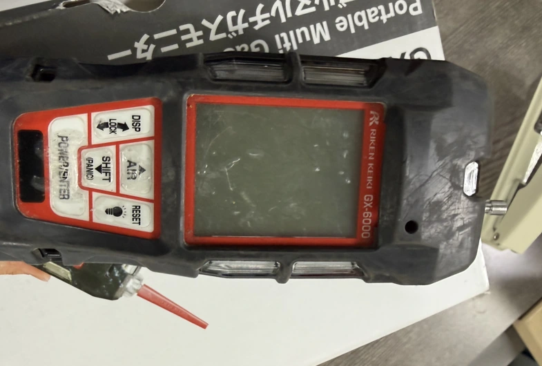
Before using a portable detector around a fixed detector, match its sensors to the gases being checked. Record the sampling location separately from the fixed detector’s alarm status.
The equipment example is the RKI GD-70D, using its official documentation. Detection gas, sensor and output specifications vary within the series. Appearance alone does not establish suitability for every gas or location. In particular, the manual states that this detector is not explosion-proof.
Inlet, tubing and exhaust form one sample path
For a sampling detector, identify the instrument location separately from the gas collection point. A detector symbol on an office wall does not mean the instrument measures the air at that wall. Trace the other end of its sample tube and confirm that the identification remains consistent along the route.
The GD-70D manual assumes sampling at normal atmospheric pressure. Direct connection to a pressurised process line is a different arrangement. Excessive pressure must not reach either port, and sampled gas must exhaust to a safe place. Discharging a toxic sample into a walkway below the instrument would create another exposure path even if detection worked.
Condensate can obstruct flow and absorb some gases. Kinks, leaks and dirty filters also affect sample delivery. Applying test gas beside the detector is not the same test as checking transport from the actual sampling point: one checks the sensor end, while the other includes the upstream route.
- 1 Actual sampling pointmatch it to plausible gas movement so the intended sample can arrive.
- 2 Sampling line and filterCheck blockage, leaks and condensation to assess sample delivery to the sensor.
- 3 Sensor and bodyMatch the target gas to the sensor specification before reading the value.
- 4 Status signalsRead concentration together with fault and maintenance status to distinguish the meaning of a fixed output.
- 5 Receiver, buzzer and alarm lampTest actual alarm delivery at the site as well as sensor response.
Sample discharge: to a safe location specified by the manual
Response time includes more than sensor response. Sample transport and electronic processing also take time. After extending tubing or moving a sampling point, an earlier sensor test alone cannot describe the modified route. Record where test gas was introduced and where the response was observed.

Match gas, sensor and installation conditions
Start specification checks with the target gas. The same housing can contain different sensor technologies and ranges. Combustible-gas monitoring does not establish toxic-exposure monitoring, and an oxygen sensor does not detect other harmful gases. The nameplate, sensor identity, displayed gas name and receiver units must agree.
A potential release location is not necessarily the path the gas will take. Consider airflow, obstructions between equipment and places where gas may collect. Reconsider existing sampling points after changing the workspace or ventilation. Overlay detector coverage and occupied areas on the layout.
GD-70D installation limitations include vibration, shock, water, oil, chemicals and sudden temperature changes. An instrument cabinet also needs heat removal and maintenance access. A visible front panel is insufficient if tubing and wiring prevent removal of the sensor and prolong a monitoring outage.
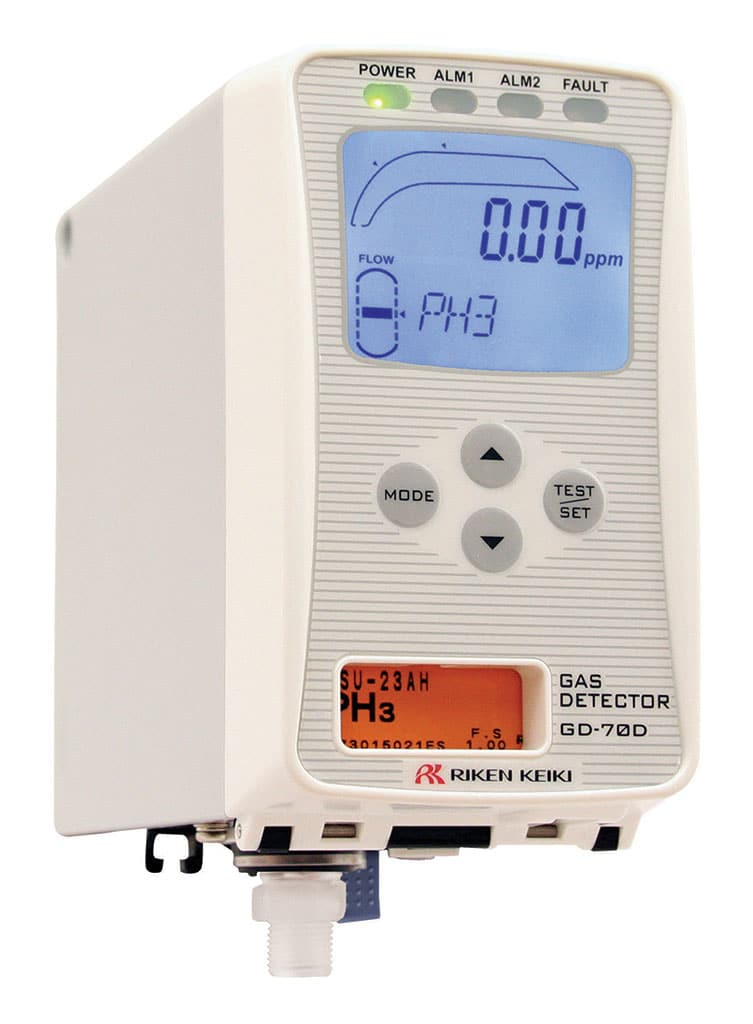
- Status lamps: check gas alarms and fault indications separately alongside concentration.
- Gas and concentration: check the displayed gas and units to identify the value for that sensor.
- Flow indication: check sample flow alongside concentration to assess the monitoring condition.
- Sensor identification window: compare the installed sensor information to confirm the actual target gas.
Read concentration, gas alarm and fault signals separately
The GD-70D distinguishes concentration display, gas alarm and fault alarm. A fault does not mean a hazardous concentration was measured, but it does indicate a problem in the monitoring function. Clearing a flow fault and continuing work because the reading is low would rely on the display without proving sample delivery.
Maintenance mode must be distinguishable at the receiver. The manual describes settings that can hold a fixed output, retain a previous value or transmit concentration during maintenance. A powered display and steady remote value do not prove unchanged ambient conditions. Show maintenance and communication status alongside concentration.
An alarm-circuit test and a gas response test answer different questions. The test function does not expose the sensor to gas. Conversely, a sensor response does not establish that a remote buzzer or beacon received the signal. A single pass box would conceal which parts were tested.
The manufacturer limits the GD-70D alarm contact to signalling devices such as buzzers and lamps and says not to use it to control a shutdown valve. This model is therefore not presented as a complete automatic isolation system. Any ventilation or isolation integration requires separate assessment of the permitted purpose and reliability of the detector, receiver and final device.
Manage the monitoring gap and prove restoration
Record the affected sampling point and maintenance period. If several items of equipment rely on one point, identify the coverage lost during maintenance. A temporary detector must be assessed for the necessary alarm transmission as well as target gas and location.
The GD-70D maintenance table distinguishes checks before work, monthly alarm-circuit testing and six-monthly regular maintenance. These are instructions for that model, not universal statutory intervals for fixed detectors. Incorporate environmental and sensor conditions and manufacturer instructions into the site plan; a calendar alone cannot describe increased dust, condensation or corrosion.
Calibration requires the procedure for the particular gas and sensor. Establish clean air before zero adjustment and use the specified calibration gas for span adjustment. Zeroing in contaminated air can distort subsequent readings. Check the sensor-specific table and procedure before using another gas or a conversion factor.
Completion extends beyond replacing the sensor. Reconnect the filter and tube, confirm flow and detection mode, and restore the receiver’s maintenance and alarm-inhibit states. Compare temporary test settings with operating settings. Records should distinguish equipment and sensor identity, test gas and expiry, values before and after adjustment, and the extent of remote-alarm verification.
A tank release without a gas warning
On 17 March 2019, a failed pump mechanical seal released butane-enriched naphtha at the ITC Deer Park terminal. The CSB final report describes the absence of flammable-gas detection around the tank and an undetected release lasting about 30 minutes before ignition.
The CSB recommended detection and alarms in storage and transfer areas, together with response planning and operator training. This was a coverage gap, not a demonstrated failure of a particular sensor. It is a reason to ask separately whether detection exists and whether an installed system functions.
For the relationship between detector location and alarm settings in a toxic-gas investigation, see the DuPont La Porte article.
Check both the legal duty and product suitability
Article 232(2) of Korea’s Rules on Occupational Safety and Health Standards addresses gas detection and alarms for the vapour or gas hazards specified there. Its proviso concerns a Korean Standard Zone 0 or Zone 1 hazardous location where explosion-protected electrical equipment is installed under Article 311. Neither the duty nor the proviso should be detached from these conditions.
Article 299 sets measures against acute-toxic-substance releases, including detection and alarm equipment. Explosion detection and acute-toxicity detection are not automatically the same sensor or setpoint problem. Match each applicable provision to the substances, equipment and work involved.
Article 311 requires verification of explosion-protection suitability for electrical equipment in hazardous areas. The GD-70D is identified as non-explosion-proof in its manual and therefore cannot be selected for installation in an explosive hazardous area. For other products, verify the exact model, certificate, gas group, temperature class and installation conditions; do not judge explosion-protection marks or foreign certifications from photographs alone.
Look for changes rather than only a normal-status tick: changed substances or ventilation, relocated sampling points, and output inhibition left after maintenance. Each can change effective monitoring even when the instrument’s exterior remains unchanged.