Verify pressure-relief protection routes and hand over status
Trace the protected equipment through the relief inlet and outlet to its destination, and hand over the basis for isolation states and unresolved segments.
Identify the equipment protected by the valve
Before judging a relief valve’s appearance, identify the equipment it protects. Connect vessel and valve identification to drawings and management information and trace the route by which fluid reaches the valve under current operating conditions. Confirm the same objects with the equipment owner where several similar units coexist.
Article 261 of the Occupational Safety and Health Standards Rules addresses overpressure protection for applicable equipment, including pressure vessels. Verify applicability and the installation basis against equipment type and conditions. Do not assume every vessel requires an identical arrangement.
Record equipment and valve identity and the applicable drawing scope together. Keep mismatches open for verification. Where documents or the protected relationship are unclear, obtain confirmation from operations and equipment owners rather than recording normal condition from appearance alone.
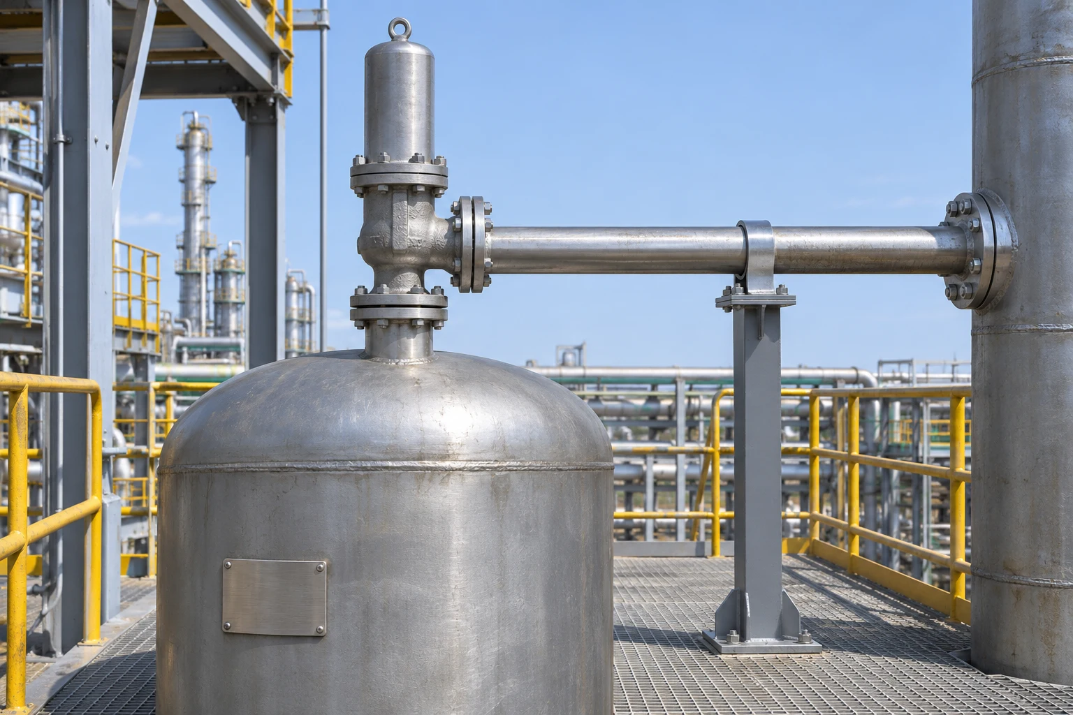
- Equipment plate: match the protected equipment to drawings and management information.
- Relief inlet: verify the route from protected equipment and identify the valve.
- Discharge pipe: connect destination and treatment basis and retain unknown segments.
- Pipe support: identify and report visible deformation, loading or changes by location.
Trace inlet and outlet routes separately on drawings
Separate the route from the protected equipment to the relief inlet from the route from the outlet to its destination. Match inlet and outlet identity to the actual installation and identify branches and junctions for verification. Nearby pipes are not necessarily part of the same protection path.
Identify intervening components on the inlet route from applicable information. Separately establish the outlet destination and treatment basis. Distinguish directly observed segments from drawing-only information and keep inaccessible or unidentified sections explicit. Mark the point where a pipe disappears behind a structure. If its identity with a pipe visible elsewhere is unconfirmed, retain the discontinuity pending drawing and equipment-owner verification.
Report the location and connected objects where drawings differ from the installation. Resolve uncertain routing through records and competent owners rather than operating valves to discover the path. Distinguish external identification from actions changing operating conditions.
Distinguish the isolation-valve rule from its exceptions
Article 266 establishes a general prohibition on isolation valves before or after pressure-relief devices together with enumerated exceptions, including conditions concerning lockable or equivalent arrangements. Where an isolation valve is present, verify the applicable basis and exception with the owner and compare the approved arrangement with the installation.
Presence alone does not establish a violation or justify telling a worker to open it. Normal, standby and maintenance paths can have different states. Verify the active route and approved position from records. Report lock or seal discrepancies together with the affected part and current operating conditions.
KOSHA Technical Support Regulation (KOSHA GUIDE) C-C-90-2026 addresses isolation procedures, active relief-valve identification, locking in appropriate positions and authorised unlocking. Connect approved states to responsible people rather than generalising that every valve must remain open.
Handover sequence
| Stage | Owner | Decision or check | Record |
|---|---|---|---|
| Protected equipment | Operations and equipment owners | Equipment, valve, installation basis | Identity and documents |
| Trace routes | Equipment owner and verifier | Inlet, outlet and destination | Drawing, observation, unknowns |
| Isolation state | Authorised owner | Rule, exception, active path, approved position | Basis, lock, responsibility |
| External condition | Site and equipment owners | Support, change and obstruction concerns | Observation, scope, request |
| Technical review | Equipment and process reviewers | Pressure, capacity, treatment, change records | Applicable conditions and open review |
| Handover | Operations, maintenance and recipient | Operating, standby, maintenance and open work | Current state and next owner |
Verify the discharge destination and treatment basis
Trace the outlet to its documented destination rather than stopping at the first visible segment. Identify shared headers and collection or treatment connections and compare them with drawings. Connect hidden sections to responsible verification and keep an unknown destination open.
Article 267 addresses treatment of discharged hazardous substances by methods such as combustion, absorption, washing, collection or recovery, with listed exceptions permitting discharge after routing to a safe place. Verify the applicable method and basis rather than requiring every outlet to use the same treatment facility. Do not improvise atmospheric or drain connections.
C-C-90-2026 addresses discharge treatment and risk assessment before connecting to environmental treatment facilities. Refer proposed route changes for competent engineering review and change procedures. Distinguish visible continuity from verified treatment conditions and communicate responsibilities and open review.
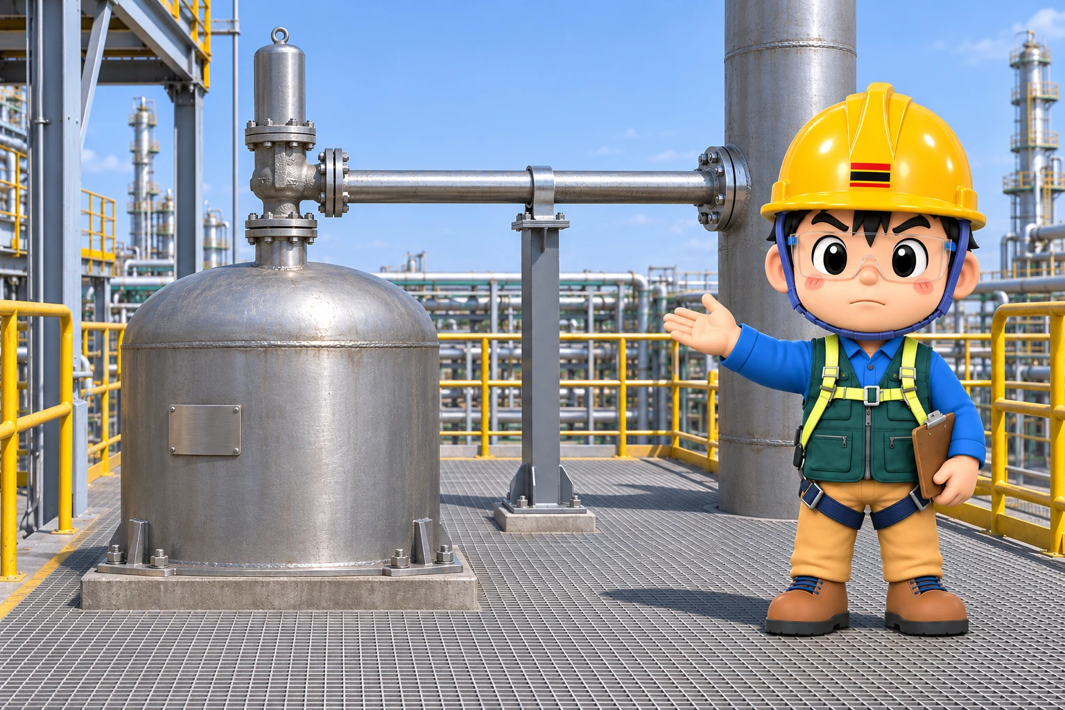
Report support and obstruction concerns by location
Observe accessible supports and connections. Link missing or deformed supports and external loads from nearby objects to their positions on the route. Do not force access to heights or restricted areas; identify unobserved sections for appropriate follow-up.
C-C-90-2026 addresses prevention of fluid accumulation, support for loads and forces, and blockage prevention. Report externally visible abnormalities and changes for competent assessment. Visible connection alone does not establish an unobstructed interior or sufficient discharge capability.
Do not investigate suspected obstruction by removing caps, drilling drains or striking pipes. Report the location and observation to operations and equipment owners for assessment. Compare insulation or support changes with authorised information and keep unknown conditions explicit.
Connect pressure and capacity requirements to evidence
Articles 264 and 265 address operating pressure and discharge capacity requirements. Match the identified valve to its setting, calculation and test documentation. Do not infer suitability for current overpressure conditions from appearance or size; connect evidence to equipment owners and competent reviewers.
Identify the operating conditions and arrangement covered by each result. Request applicability review where equipment or routes have changed but only old records remain. Do not resolve unclear information by having workers adjust set pressure or conduct an improvised test.
Separate identity, checked scope and remaining conditions in maintenance or inspection handover. Connect valve-specific results with inlet and outlet route status, without using one to close unknowns in the other. Record the evidence scope and open items for the next responsible person.
Use KOSHA checklists within the relevant equipment scope
The pressure-vessel checklist in KOSHA Practical Guide 69 for Other Chemical Product Manufacturing identifies relief valves, rupture discs, intermediate instruments and inlet isolation conditions. Use it to identify components to locate while retaining current legal exceptions and equipment design conditions.
The same guide’s reactor checklist includes outlet collection and treatment connections. Keep that reactor example distinct rather than attributing it to the pressure-vessel table. Verify the actual discharge arrangement against Article 267 and relevant design information.
Record the protected equipment, inlet and outlet connections, active route, evidence and unknowns separately as a handover method. Distinguish competent technical review from external observation instead of marking all legal and technical conditions complete from appearance alone.
Hand over operating, standby and maintenance states
At shift or maintenance handover, communicate the active protection route and its basis. Distinguish standby and maintenance paths and connect approved positions and lock control to responsible people. Recipients compare actual state with the handover within their verification scope and report discrepancies.
Separate completed and open actions during route changes or abnormality handling. Assign follow-up for drawings, identification, locks and discharge destinations. Have authorised owners determine operating conditions and necessary protection while work remains open; do not change valve positions informally. Retain the owner and verification scope of each unknown when recipients change. Have authorised owners distinguish current operating-path concerns from items for later maintenance and communicate that decision to relevant departments.
Close the check by ensuring the same path from protected equipment through the relief valve to its destination can be identified in records and the installation. Retain applicable rules and exceptions, checked scope and pending technical review. Make present state and change history distinguishable to the next owner.
Related reading
Original sources
- Korean Occupational Safety and Health Standards Rules — Articles 261, 264, 265, 266 and 267
- KOSHA Technical Support Regulation (KOSHA GUIDE) C-C-90-2026 — Sections 8.2–8.4, printed pp. 27, 31–32
- KOSHA Practical Guide 69: Other Chemical Product Manufacturing (2023) — reactor printed p. 170; pressure vessel printed p. 172