Line breaking: identify the pipe, isolate energy and verify conditions
Identify the opening, then trace its connections
Opening a line begins before bolt removal: identify the exact connection and every path capable of supplying material or energy. A report that operation has stopped does not establish depressurisation or removal of contents at the opening. Connect isolation, draining or purging and residual-hazard checks to that point.
Even with the correct line designation, a branch or bypass may be absent from the isolation list. A short work section does not justify checking just one valve. Maintenance can expose different flow paths from normal operation, so reconcile drawings with the installed system.
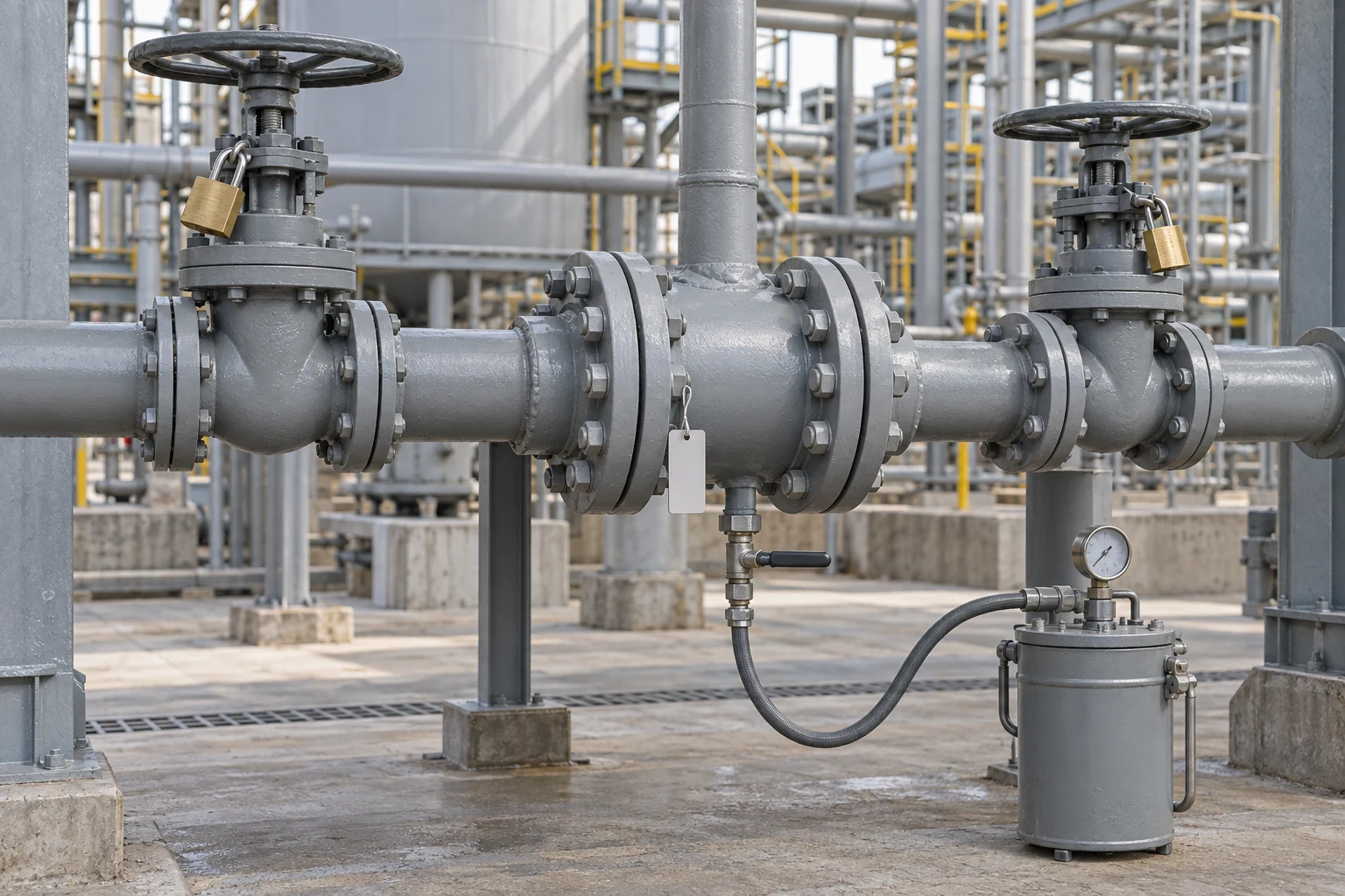
- Flange and tag: Before loosening bolts, match the work scope to the site identification and confirm the opening point.
- Isolation valve: Cross-check the upstream, downstream and connected paths, and confirm who controls locking and release.
- Drain and collection vessel: Before draining, inspect connections and the collection route, then check residual pressure using the specified procedure.
- Branch pipe: Trace branches from the work point to check for other supplies and bypass connections.
What a closed valve can leave behind
The first issue is another supply path: bypasses, branches or connected operating equipment. With several jobs on the same line, draining or restoration for one team can affect another opening. Mapping each work boundary reveals shared isolation points.
The second issue is trapped contents. Liquid in low points and poorly drained sections does not disappear when a valve closes. A drain’s presence does not prove effective, safe drainage. Determine where material will go and whether the route creates exposure or affects other equipment.
The third issue is the relationship between verification and opening points. A blockage or separation between a gauge and the flange can invalidate the inference. Loosening bolts is not a substitute for an established safe verification method.
Figure 2 highlights the checks described here.

- Main pipe: relate the closed valve to the actual isolation boundary.
- Bypass: trace alternative inflow routes beyond the main line.
- Verification point: identify where pressure and contents relevant to the work point are checked.
- Opening flange: verify that the isolation boundary covers the joint to be opened.
Taking the drawing to the equipment
Match the permit’s equipment, line and opening location to field identification. With similar adjacent lines, direction or colour alone is insufficient. Identify the actual connection, then determine whether the isolation list encloses it, including temporary hoses or bypass arrangements.
Select isolation for the material hazard and work. A generic list cannot establish that a particular valve arrangement is adequate. HSG253 treats preparation, installation, proving, maintenance and restoration as one process. Installation leaves further duties to verify and preserve the state throughout the job.
Assess the hazard of both the removed material and the cleaning or purging medium. Discharge volume or smell alone does not establish internal safety. Verification needs representative locations and suitable methods, with attention to blocked or separated sections that the check may miss.
Immediately before opening, reconcile the current job and isolation with the prepared state. Stop for mismatched identification or unexplained drainage and resolve it with the relevant people. Tool readiness does not justify postponing the discrepancy; extra protective equipment does not establish a safe opening condition.
At completion, verify closure and temporary arrangements and hand over restoration authority. Check other jobs sharing the isolation first. Restoring supply when only one task is finished can feed another open section. The restoration record must connect to the original isolation record.
Isolation is needed before inserting the blind
A planned blind must first be installed, often through an opening. HSG253 distinguishes initial valve isolation and depressurisation from installation of the final isolation. Planning a blind does not remove the preceding opening hazard. Assess its installation as line-opening work.
Account for contents between the initial isolation valve and the flange. Marking the final isolation point is different from making it safe to open. The preparation must address removal and verification for that intervening volume, not authorise only the intended end state.
Remote valves differ in their response to loss of motive power. HSG253 distinguishes designs that need power to close from those that close on loss of power. Disconnecting power does not necessarily preserve fluid isolation. Verify the effective valve state after power isolation using the equipment information and defined method.
Distinguish a cover keeping debris out from a pressure-retaining closure. HSG253 addresses pressure rating, gaskets and fastening suitability. Similar appearance does not make a temporary cover suitable for pressure; determine the conditions it will face during restoration.
Leakage past a valve can accumulate material behind a blind. Removal must not assume the original insertion conditions still hold. HSG253 therefore addresses both installation and removal. Reassess the removal point and connect drainage and verification to any volume where material could have accumulated.
The isolation plan should remain understandable to both the installer and the restoration team. Recording insertion without the removal conditions postpones crucial decisions. Linking location, shared work, remaining hazards and restoration authority is a practical way to reduce that gap.
The provision for chemical-equipment disassembly
Article 278 addresses specified disassembly or internal work for modifying, repairing or cleaning chemical equipment and associated equipment. Apply its supervision and measures concerning hazardous release, hot steam and surrounding concentrations to the qualifying work. It is not an identical legal requirement for every pipe job.
HSE HSG253 is British technical guidance supporting assessment of isolation and verification; it does not replace Korean law. The actual method, opening sequence and protective equipment must reflect material information, equipment procedures and applicable requirements.

Questions to reconcile at the flange
Record evidence tied to the opening rather than just “isolation complete”. When the list and field arrangement disagree, investigate the reason and redefine the boundary rather than adjusting a number to make the paperwork match.
| Point | Question | Follow-up |
|---|---|---|
| Opening | Do permit and actual flange match? | Verify field identification and drawing |
| Bypass | Could a path supply the opening from outside the boundary? | Include branches and temporary connections |
| Shared isolation | Could another team’s restoration affect this opening? | Confirm the status of connected work |
Reassess when the task changes
The flange-opening sequence and blind specification must suit the equipment’s pressure, temperature and construction. Pressure, temperature, fluid and geometry determine the controls. Opening conditions require equipment-specific procedures and competent assessment.