Electrical isolation: is the isolated circuit the one you will work on?
Between the locked isolator and the equipment
An isolator is locked and tagged. A worker is preparing to open terminals on equipment some distance away. Has the supply path between the two points been identified? De-energized work starts with choosing the isolation point and extends to checking the electrical state of the parts that will actually be touched.
Cutting power, preventing re-energization and checking whether the equipment is energized answer different questions. A visible padlock alone cannot establish that every supply to the equipment has been isolated. Other supplies and stored charge may remain relevant. Match the drawing to the equipment identification before following each protective measure.
Article 318 of the Rules on Occupational Safety and Health Standards (산업안전보건기준에 관한 규칙) requires qualified persons for installation, dismantling, maintenance and inspection of electrical equipment or circuits where electric-shock risk exists. Inspection here is limited to using equipment or tools to check the effectiveness of the installation. The questions below support work-plan review. Actual work depends on qualified persons who can assess the equipment and the applicable procedure.
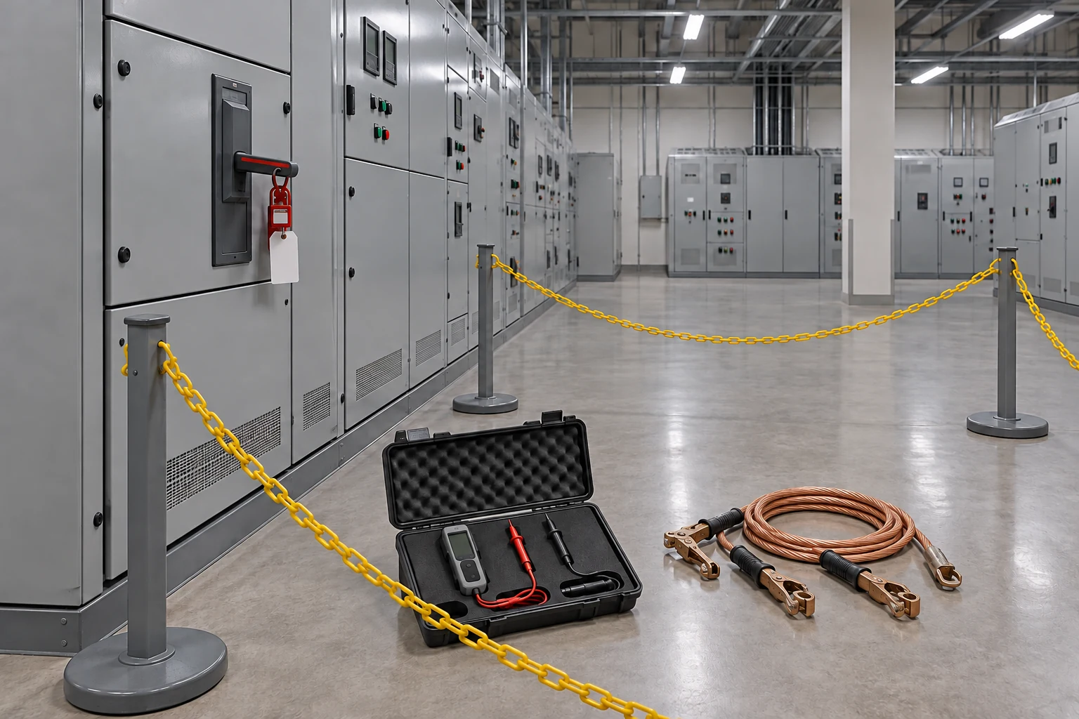
- Lock and tag: Before work, confirm the isolation point and the person responsible for locking, and agree the re-energization procedure.
- Voltage testing tools: Before work, test the target circuit to verify the absence of voltage, and check the instrument operates before and after use.
- Portable grounding equipment: Connect it after testing has confirmed the absence of voltage; inspect connections and cables for damage first.
- Work cordon: Before approaching, confirm the work limits and access boundary.
Separate supply paths, stored charge and possible incoming voltage
Article 319(2)1 requires all supplies associated with the work to be identified from drawings, wiring diagrams and similar information. Trace the paths into the work area rather than stopping at the first supply found. If equipment identifiers on the drawing and in the field differ, resolve which circuit is to be isolated first.
Under Article 319(2)4, residual charge must be fully discharged before contact when induced voltage or stored electrical energy presents an electric-shock risk. This separates a disconnected supply from the absence of remaining charge. Item 5 then requires a voltage detector to check whether the target equipment is energized. The test location should make the relationship between the locked isolation point and the actual work area clear.
Short-circuit earthing also depends on conditions. Item 6 requires earthing equipment of sufficient capacity where voltage may arise through contact with other exposed live parts, induction or backfeed from a standby source. Review the relevant incoming-voltage risk and the suitability of the earthing equipment together in the work plan. Start with the circuit conditions rather than applying one earthing arrangement to every job.
- Identify supplies: All supplies on drawings and wiring diagrams.
- Isolate, open, lock and tag: Target equipment and isolation boundary.
- Discharge and test: Stored-charge risk and target voltage state.
- Conditional short-circuit earthing: Contact, induction or backfeed risk.
- Check before restoration: Remove tools; clear workers; installers remove locks; check abnormalities.
What belongs in the work plan
Article 38(1)5 covers a written work plan for electrical work under Article 318 where the relevant voltage exceeds 50 volts or electrical energy exceeds 250 volt-amperes. These are the conditions stated for that work-plan requirement. The scope of qualified-person work and de-energization measures under Article 319 require their own conditions to be considered separately.
Annex 4, item 5 includes the purpose, qualifications and staffing, scope and responsibilities, identification of hazards such as electric shock, arc flash and arc blast and approach limits, circuit-isolation work planning and power-restoration procedures under Article 319, temporary operation for inspection and trial runs, suspension and handover, and exclusion of unauthorized persons. A sheet containing only an isolator number offers little explanation of how these conditions fit together. Marking both the isolation boundary and work scope on the drawing helps explain the plan.
What if inspection or a trial run requires temporary operation? The annex entries on temporary operation for inspection and trial runs, interruption and handover provide a basis for identifying who stops and restarts work, and in what state. Communicating the work plan under Article 38(2) also helps each worker understand the relevant boundary and sequence.
From isolation to restoration: where the checks change
After cutting the supply, open and check disconnecting devices. Attach locks and tags to the disconnecting arrangements. Check discharge where residual charge poses a risk, test the target equipment for voltage and apply short-circuit earthing when required. Locking and voltage testing address different matters: re-energizing actions and the present electrical state.
At completion, attention moves from the parts being worked on to the restored condition of the circuit. Article 319(3) requires removal of tools and short-circuit earthing equipment and verification that the equipment can be safely energized. It also requires confirmation that all workers are clear. Linking installation records to removal checks helps identify equipment that may have been left in place.
The same paragraph requires locks and tags to be removed by the worker who installed them. Power is then restored after checking for abnormalities. When a shift change or handover changes the people involved, identify whose lock is present and which work has finished so that the restoration checks can proceed.

Questions to ask with the drawing open
Which terminals or equipment identifiers define the job, and have all supplies to those points been traced on the drawing? Resolve mismatches between field labels and drawings before work. Recording the work area alongside the isolation status helps keep the scope visible instead of hiding it behind a single “isolated” entry.
Under what conditions could stored charge or incoming voltage remain relevant? Discuss the tested equipment, parts requiring discharge and conditions for short-circuit earthing separately. This makes missing measures easier to identify. Selection and use of voltage detectors and earthing equipment depend on the equipment conditions, ratings and procedures.
Who will check remaining work, people and tools before restoration, and how? Connect removal of locks by their installers, worker clearance, removal of equipment and checks for abnormalities with the completion record. These recording methods are editorial recommendations. Site forms and retention requirements are determined separately under the applicable rules.
Questions that depend on the installation
Article 319(1) contains exceptions to isolation, including circumstances where cutting power would increase danger. Applying an exception requires a separate assessment of the reason and work conditions. It is not a general permission for workers to omit locking or approach live parts.
Voltage class, earthing-equipment capacity, detector suitability and actual isolation points depend on the installation documents. The educational model distinguishes the isolation point from the equipment to be checked. Connection methods and numerical requirements must be resolved through the installation drawings and work procedure.