Blinds and LOTO devices: stopping fluid and preventing operation
A locking device has a different role from a fluid barrier
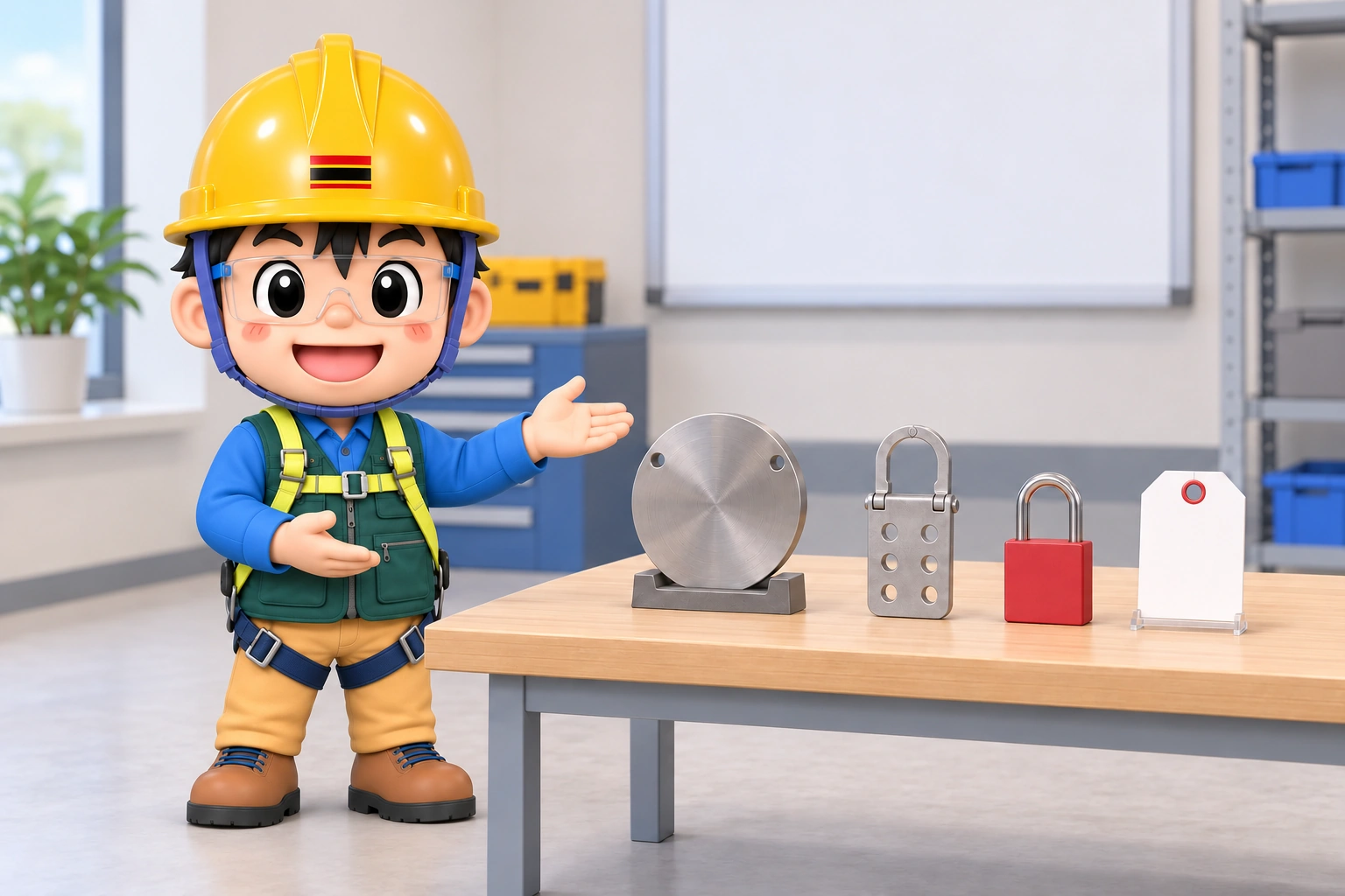
A blind physically blocks the fluid passage. A locking device prevents unauthorised operation of a valve or isolator, or access to bolts securing a blind. A tag identifies the restriction and the work or person associated with it. Calling all three “isolation” can hide which component actually stops the energy.
The line must be opened to insert a blind and again to remove it. Initial isolation must protect those operations as well as the final work. Seeing a closed valve is different from proving that it remains leak-tight.
Piping-isolation components have different functions and limitations. SM-003 covers the overall work-permit procedure, while SM-010 addresses decisions about opening piping. Here, component selection, positive identification of the installation location, and checks for residual pressure and leakage are considered separately.
Distinguish the blind, bolt lockout and tag
A spade is a solid plate inserted in a joint; a blind flange closes a pipe end. A spectacle blind joins a solid plate to an open ring. In each case, resistance to the fluid and pressure depends on a suitable component and joint. A visible handle or marker does not establish material, pressure rating or orientation.
The Master Lock S3922 shown is a blind-flange lockout device. Its stated purpose is to conceal flange bolts and prevent access. The red device is not the pressure-retaining plate in contact with the fluid. Its presence cannot replace an absent or unsuitable blind.
Select a device that fits the actual bolt arrangement and blocks access when locked. A photograph of a closed padlock does not establish correct installation. Check the assembled arrangement for tool access, movement, detachment and proper engagement of the lock holes and padlock.
- 1 Fluid sourceTrace the main pipe and other inlet paths to identify connections that can admit fluid.
- 2 Blind: blocks fluidCheck the blind’s material, rating and joint for fluid isolation separately from the lock’s role.
- 3 Bolt lockout:Check actual restriction of bolt access as well as installation appearance.
- 4 Work side: verifyCheck residual pressure and pressure return alongside the gauge reading before following the opening procedure.
- 5 Tag: identifiesMatch the current permit, location and tag to confirm the opening conditions for this job.
A tag communicates a restriction without physically restraining movement. A padlock and tag are not interchangeable either. OSHA 1910.147 distinguishes a tag’s restraint from a lock and separately requires stored-energy control and verification of isolation. These US requirements are not presented as identical statutory wording for every Korean task.
Find every connection entering the work boundary
An isolation boundary includes more than the name of the equipment being worked on. Bypass, drain, cleaning and instrument connections may enter it as well as the normal supply. Link each potential energy path to its isolation point. Connection relationships matter before the hardware count.
HSE HSG253 distinguishes initial valve isolation, depressurisation and draining from installation of the final physical barrier. A drawing showing only the final blind leaves unanswered what protects workers before it is installed. Assess insertion and removal within the isolation plan.
When a normally closed valve is used as an isolation point, match its identity to the actual line. Adjacent similar piping and distant tags can lead to selection of another flange. Permit description, isolation drawing and direct field identification must refer to the same component.
Current identification must be distinguishable from old markings. Paint from previous work or a locking device left from another job must not become the identifier for the present opening. Match the positively identified point to the currently authorised task.
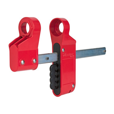
- One shielding side: identify where bolt access is restricted and distinguish that role from a fluid barrier.
- Connecting bar: compare the actual flange arrangement and connection to check installation fit.
- Locking positions: verify actual padlock engagement and locking before checking readiness for work.
A low gauge reading does not complete verification
After isolating a line, address remaining pressure, temperature and contents. A low gauge reading does not prove that every section is empty. A drain may be blocked or the gauge range may not resolve low pressure adequately. Checking that a vent or drain works and leads to a safe place is different from reading a gauge.
HSG253 describes verifying leakage and pressure build-up inside the isolation envelope by an appropriate method immediately before opening and monitoring integrity during work. Define the method and acceptance criteria during planning. Workers must not be made to discover leakage through exposure.
Consider the destination of discharged material. Moving it from a pipe into a walkway or low area may reduce danger at the opening while exposing people nearby. Assess the discharge destination and possible backflow from connected live systems.
Control conditions that could recreate pressure through temperature change or inflow. Long-duration or multi-shift work needs a defined re-verification method and timing, not merely a handover of the original result. Set these for the fluid and isolation method rather than inventing one interval for all plant.
When lockout hardware was mistaken for an opening marker
On 10 October 2024, hydrogen sulfide escaped during blind removal at PEMEX Deer Park, killing 2 people and injuring 13. The CSB final report describes workers opening a live line other than the intended piping.
Investigators found that the crew looked for flange-locking devices familiar from earlier maintenance. Those devices were intended to secure installed blinds, not serve as standard identifiers for equipment to be opened. An unlocked device on the wrong line became a location cue.
The CSB identified weaknesses in positive identification and useful detailed drawings. Stronger locking hardware alone would not resolve this problem. What is being secured and what may be opened need separate verification. This account does not identify the pictured S3922 as the incident device or present it as a failure of that manufacturer’s product.
Bolt coverage and key control need different checks
Before use, inspect the lockout body for deformation and cracks, moving parts for binding, lock holes for damage and the padlock for proper closure. Check for interference with the actual equipment. Filing or enlarging a part to force a fit can change the manufacturer’s intended engagement.
Inspect the blind separately: suitability for fluid, temperature and pressure, joint faces, gasket, bolting and identity. A robust-looking lockout body cannot establish a blind’s pressure suitability. Keep the two component checks separate in the record.
With multiple workers, make continuing protection visible. A group lockbox or multiple locking points still needs entry, withdrawal and shift-change procedures. Do not make removal of another person’s lock a routine convenience; define exceptional authorisation and verification explicitly.
Before restoring energy, verify that people and tools are clear and equipment is restored. Removing a blind is itself line opening, so address possible pressure behind it again. Reconcile removed and retained blinds and restored valves with the final list before operation.
Read Korean provisions with their scope
Article 92 of Korea’s Rules on Occupational Safety and Health Standards addresses stopping machinery for hazardous maintenance and related work, with protective measures such as locking or marking the starting device against operation by others. It also has a proviso for machinery structure and safety measures. It is not a universal specification for piping-blind design.
Article 278 concerns dismantling and internal work on chemical facilities and accessories. It addresses work direction, prevention of hazardous-material or hot-steam leakage and flammable-atmosphere measurement around the workplace. Issuing a permit does not establish component suitability or completed leakage prevention.
Environmental wording on a Master Lock product page is not an individual Korean approval certificate. Match exact model documentation to actual dimensions and conditions. HSG253 is UK technical guidance, separate from Korean statutory duties.
It is useful to record blind identity and installation or removal status, the application of locking devices and padlocks, pressure-check results, and positive identification of the opening point separately. Completion of one item is not evidence of the others; this reduces confusion between the appearance of installed hardware and the actual conditions permitting work.